


We’ve owned Mai Tai for 28 years and on average have installed new batteries every six years. That’s five sets of costly, large lead blocks, and we’d grown tired of living with their inefficiency, weight and expense.
For most boats with lead-acid batteries, the charging process is frustrating because the closer they get to being full, the greater the resistance to absorb charge current. This ‘diminishing-charge-acceptance-rate’ is a problem irrespective of the charging source.
At best, solar panels are only 17 percent efficient at converting solar energy to DC current. And if the batteries are 75 percent full, most of that current is turned away by the batteries.
The same is true with alternators. We use a Balmar 165-amp alternator, but most of the time it’s charging between five and 25 amps because the batteries turn away the available charge current. Consequently, the engine must run much longer to achieve a full charge. This becomes even worse as the batteries age.
And there’s more.
In addition to being difficult to charge fully, lead-acid batteries only give back about 40-50 percent of their rated capacity (amp-hours) between charges. So if you require 300 amp-hours (ah) of useable energy for your electrical needs, you will need a battery bank rated at 600ah or more. That battery bank will weigh over 175kg and require a lot of space.
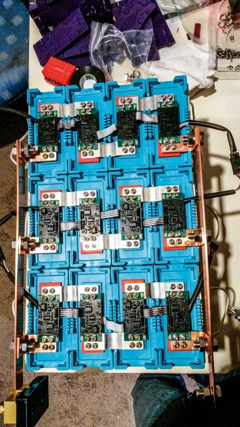
We didn’t want to put another set of lead-acid batteries on Mai Tai. So we began researching lithium-iron-phosphate (Lifepo4) batteries. What we found was much simpler than we’d expected, considering all the scary stuff that’s been written about them.
Performance Comparison
How are Lifepo4 batteries superior to their lead-acid cousins? Here’s a quick overview.
Lifepo4 batteries will take a charge current equal to their amp-hour rating, right up to their fully-charged state. Theoretically, you could top-up a fully-discharged 300ah bank of lithium batteries in an hour if you had a 300A charger.
They don’t care if they are fully-charged or only half-charged. In fact, when stored for long periods they prefer being half-full and they will lose less than two percent of their charge per month. Over six-months the battery level may drop by 12 percent.
Lifepo4 batteries can give back about 80 percent of their rated amp-hours and not be seriously discharged. If you need 250ah of useable power, a 300ah Lifepo4 bank will be plenty.

Even as Lifepo4 batteries are discharged they maintain a very steady voltage level. This is good for your boat’s electronic load though it does have one disadvantage; it makes it very difficult to measure the state of charge (SOC) of your bank using voltage readings alone.
Compared with a same-capacity lead-acid bank, Lifepo4 batteries are generally a third of the weight and less than a third of the volume.
Aren’t they a fire hazard?
It turns out the problem’s not with the batteries but with your boat’s existing infrastructure.
AC chargers, alternators, solar regulators and wind generators are all charging sources for batteries. They’ve all been developed for lead-acid batteries – and they’re not always suitable for a Lifepo4 bank.
But by making some minor adjustments to your charging infrastructure, you can massively improve power and efficiency. Yes, this comes at a cost, but it’s a one-off.
Here’s an outline of the changes required:
The lead-acid charging regime usually has three steps – bulk, absorb and float. A Lifepo4 charging regime has two steps; bulk and off. There is no need for the absorption phase. Note: Lifepo4 batteries don’t like continuous float charging – it shortens their life.
Alternators use regulators designed to charge lead-acid batteries, but these regulators don’t suit Lifepo4 batteries. Some companies, however, have developed regulators for Lifepo4 batteries. Balmar’s new MC614 regulator is one of them.
Solar panels use a controller for charging batteries and it needs to be adjusted to suit Lifepo4. Thanks to the growth of off-grid, solar-powered homes and RVs, there are now several suitable solar controllers on the market.
A wind generator must also be regulated for a Lifepo4 bank. It must automatically shut down before the batteries are over-charged.
The AC chargers we use with shore power are designed for lead-acid batteries. Many tout a five-step charge regime, but this is irrelevant for Lifepo4 batteries.
Mai Tai’s birthday present
Our new system has various design features.
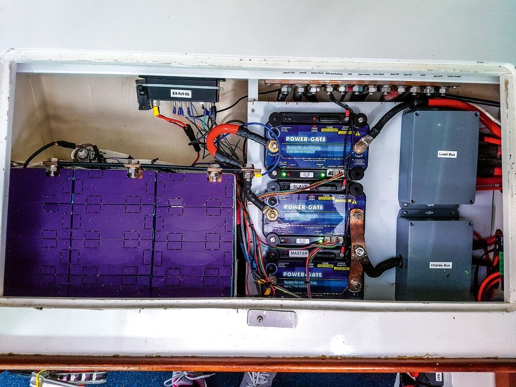
First, because Lifepo4 batteries don’t like heat (or excessive cold) we moved the battery bank to an area that’s insulated from the engine room.
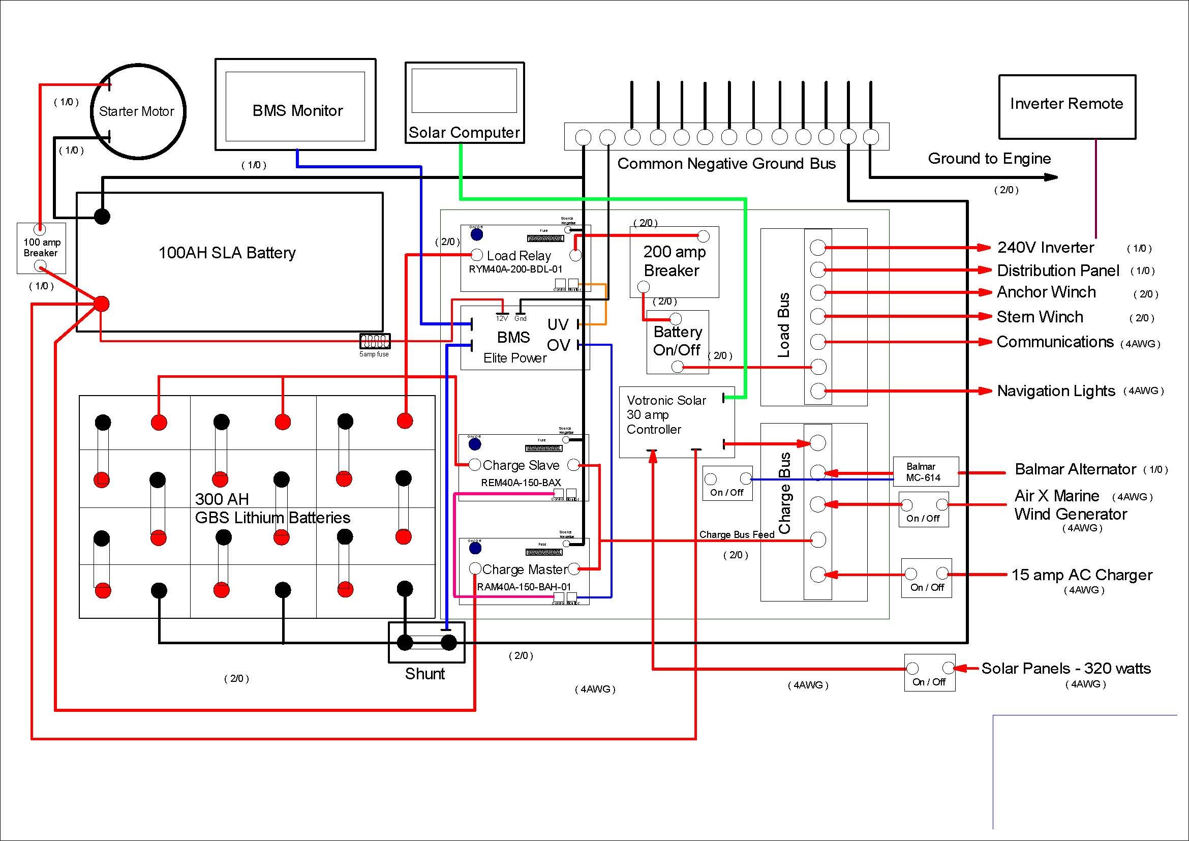
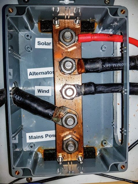
There are three bus bars – one for all charge current going into the batteries (Charge Bus), one for all current leaving the batteries (Load Bus) and a common ground bus (Ground Bus). This arrangement stops current from entering the batteries when fully-charged by switching off the Charge Bus. It stops current leaving by switching off the Load Bus when the batteries are nearly empty.
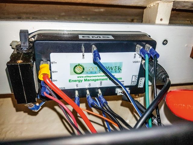
The Charge and Load Bus bars are connected to separate switches controlled by the ‘battery monitoring system’ (BMS). The BMS constantly monitors the lithium cells and tells the switches to close when set levels are reached.
Some installations simplify this arrangement by having both the Charge Bus and the Load Bus on one switch. This can be a problem: if the battery is over-charged and the switch is turned off, the Load Bus is also turned off and you can’t use the batteries.
It might keep the cost down but it prevents the batteries from being used and brought back within an acceptable charge range. Having two bus bars and two switches allows the batteries to be kept within charge limits without removing them from the system completely.
One of the issues with using relays to stop the flow of current is this: what happens if the charge relay opens when you are charging the bank? For example, if the alternator is grinding out 100 amps of current and suddenly the switch is thrown? The alternator can’t sense the battery charge level because it’s been disconnected.
This may cause wild spikes in voltage levels throughout the system and could cause some damage, including to the alternator. To solve this we put a sealed lead-acid (SLA) start battery alongside the Lifepo4 system. All it does is start the engine.
But – we designed the Charge Bus relay so that it connects with the SLA battery before it switches off from the lithium bank. So if the Charge Bus switch is opened, the alternator immediately sees the lead-acid battery in the system and adjusts its charging according to the new battery.
The Lifepo4 bank is removed from the Charge Bus but is still running the loads through the Load Bus. As the charge level falls back to within the programmed range, the relay brings the Charge Bus back online and the SLA battery is disconnected.
Keep in mind that the relays for the Charge and Load Bus are for ‘system failure’ incidents (perhaps the wind generator fails to shut down when it should). Each of the charging sources should be programmed to keep the Lifepo4 pack within its limits without throwing the relay.
Note: In the best possible design we want the whole system to operate without ever throwing one of these relays.
I’ve also seen configurations that use an SLA battery in the system and use a battery isolating relay to keep the batteries separate while allowing the Charge Bus to keep both batteries charged. With this system it’s difficult to sense true battery voltage because the isolator blocks the voltage from travelling back through the isolator to the post where it can be detected.
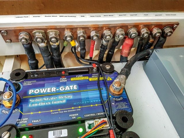
Our system has the advantage of allowing both batteries to be charged by the Charge Bus, but they cause a lot of difficulty when trying to acquire an accurate battery voltage for the alternator. For this reason we haven’t used a battery isolating relay. Instead, we have a ‘make-before-break’ single-pole-double-throw (SPDT) Mosfet solid-state relay that will comfortably handle 250 amps at 12 volts continuous.
This won’t allow us to simultaneously charge the lead-acid battery through the Charge Bus. But we have a solar charge regulator, which will put a small charge to the lead-acid battery independent from the Charge Bus. This should keep it well charged as the current draw on this battery will be quite low. In addition, we have placed a manual override switch in the system, which will allow us to bring the SLA battery on to the Charge Bus if it ever requires a quick top-up.
The Relays
We wanted a make-before-break relay for the Charge Bus, which would allow the charge bus to sense the SLA battery before losing contact with the lithium bank. This will protect the system from the charge bus throwing out stray current with nowhere to go. We also wanted the relay to have its own set of criteria for switching off in case the BMS unit lost power or in some way failed.
Perfect Switch in Southern California helped me out. It put together a Slave and Master unit for the make-before-break relay. You can see in the wiring diagram that the Slave unit is connected to the lithium bank and is normally “on”, which means it is closed.
The Master unit is connected to the SLA battery and is normally “off” or open. They are both connected directly to the Charge Bus. When there is an “event” where the BMS over-voltage pin (OV) sends out a shut-off signal, the Master unit closes just before the Slave unit opens, thereby providing a path to the SLA battery for any charge current coming in.
Since the Master and Slave units are both bi-directional the alternator is always able to get an accurate voltage reading of the battery being charged.
These relays are able to be programmed to switch off at a certain voltage so I have set them up to shut off at just a bit higher voltage than what the BMS is set for. If the BMS fails, the relays should shut off the charge bus before any damage is done to the batteries.
The Load Bus is pretty straight forward. It uses one relay, which switches off the loads when the BMS sends a message that the voltage level in the lithium bank is too low (UV). We ended up using 90 percent charged for ‘Full’ and 20 percent charged for ‘Empty’. This gives us useable amperage of roughly 70 percent of 300 amps – or 210 amps of useable power while keeping the Lifepo4 batteries well within their best operating mode.
Obviously, it is very important to have all loads from the boat connected to the Load Bus and all charging systems connected to the Charge Bus in order for this system to work properly.
Adjusting the Existing Infrastructure
To make sure none of the charging units would kill our new batteries, we did the following:
Solar – we have two 160-watt panels and settled on a Votronic MPP 350 Duo Digital solar regulator, which has switchable settings for charging lithium batteries. I also set up a switch on the panel, which allows me to shut off the solar panels completely so they won’t try to trickle charge the batteries to death when we are not onboard.
Wind generator – ours is an Air-X-Marine unit with new Blue Blades (much quieter!). This unit has an internal regulator, but also an exterior ‘pot’ screw on the body that can change the cut-out voltage on the unit. I adjusted the cut-out voltage to 14V, which should shut the unit down long before the BMS senses a critical voltage level in the lithium cells.
Alternator – this Balmar 165 has an external MC-612 regulator. Balmar says it has developed a new regulator with a Lifepo4 charging regime all set up. It also says my older model MC-612 can be programmed to suit Lifepo4 batteries. Balmar issued a service bulletin in December last year which explains how to re-program the MC-612 for lithium. Job done!
AC Charger – Elite Power Solutions distributes a small AC charger, where a control cable plugs directly into the BMS unit and charges the batteries according to the BMS readings. It only puts out 15 amps. So this unit is aboard and connected, ready to use if we ever use shore power.
Useful links
www.nordkyndesign.com/electrical-design-for-a-marine-lithium-battery-bank/
www.entropypool.de/2015/05/15/designing-a-lifepo4-battery-system-part-1-lifepo4-cells/
www.honeynav.com/wp-content/uploads/2016/06/LFP-battery-Stan-Honey-notes.pdf
www.elitepowersolutions.com/
www.per’tch.com/
About the writer: Lane and Kay Finley are cruisers with more than 30 years of bluewater sailing experience. They have promised to send an update about the performance of the Lifepo4 system during their circumnavigation.
You can follow their blog at sailingmaitai.com.
Better Batteries
Written by
Share this

Eberspacher hot air heating installation
I've installed and used various hot air heaters over the years, and the one thin...

Northland Harbourmaster warns: that cheap classic could cost you dearly
Northland Regional Council's maritime team is urging budget-conscious buyers to ...

Feadship’s Halycon, when a refit becomes something else entirely
Captain Joe Gallegos puts it plainly: "What started as a refit became something ...
Comments
This conversation is moderated by Boating New Zealand. Subscribe to view comments and join the conversation. Choose your plan →
This conversation is moderated by Boating New Zealand.