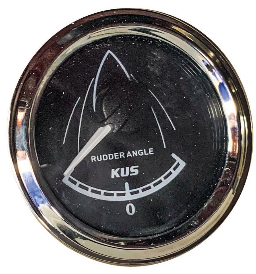
One of the useful, but not necessarily essential, gauges on the helm of a boat is an indicator showing which way the rudder is pointing.
This is of course more important on a yacht with an underslung rudder, or a launch where either the rudder or sternlegs are not visible from the helm position. Without some sort of direction indicator, you have no idea which way the boat will steer when you apply power. This could have disastrous consequences if the boat suddenly moves the wrong way.
Such an indicator is usually not required on boats powered by an outboard motor, since a quick glance backwards at the powerhead will indicate which direction it is pointing. However, if the helm position is located too far forward, if the skipper is steering from a flybridge, or even if the cockpit has an overly high transom wall, then the outboard may not be easily visible from the helm station. Another issue is a skipper with restricted neck mobility, who may find it hard to repeatedly swivel his head through 180° while manoeuvring.
A steering indicator on the dashboard may be a good option in these cases as well.
Conventional solutions have a direction sensor with an arm that is attached to the rudder. As that arm pivots a variable resistor inside the base of the unit detects the angle of the rudder and displays the position on the dash gauge. Inboard propulsion systems such as a waterjet or an IPS pod will have a similar mechanism, although it will most likely be swung by a steering rod instead of the rudder. In both cases, however, the relatively fragile mechanism is usually hidden behind a bulkhead or below decks where there is space for things to move around freely without risk of snagging.
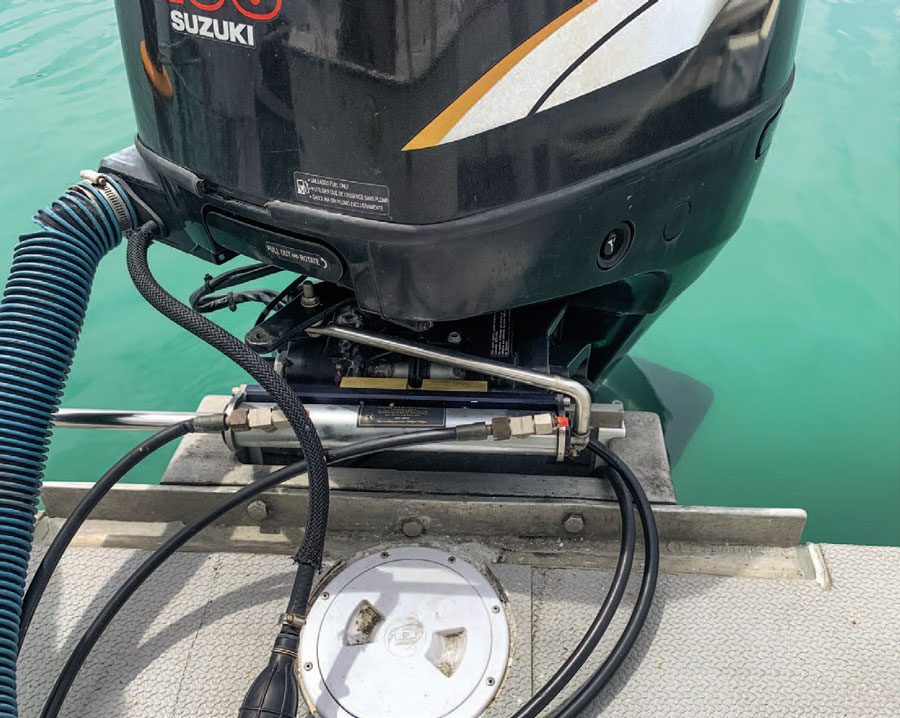
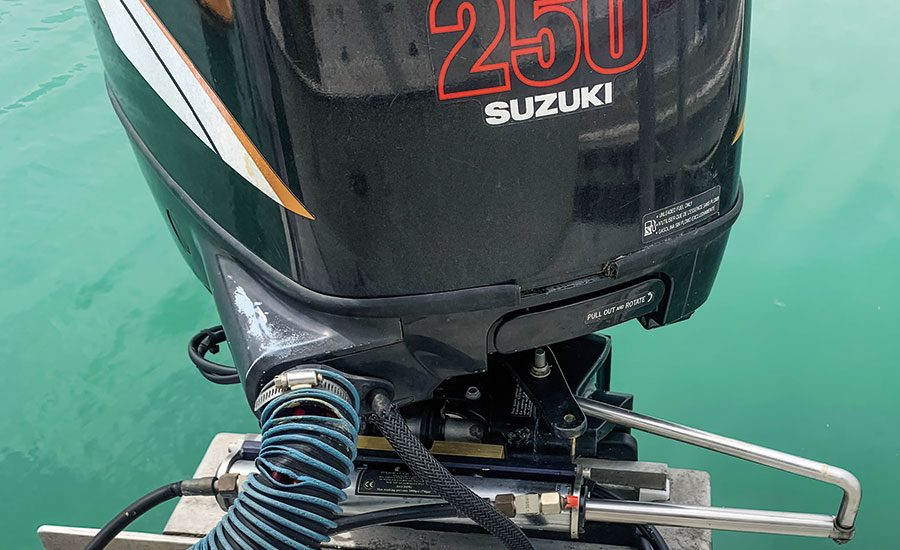
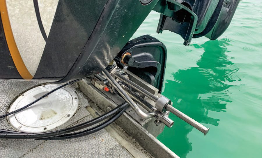
It is not so simple on an outboard-powered vessel. The motor generally sits in an open well or on the transom, and there is usually very limited space around it for things to swing around. Worse, the entire outboard tilts up, so any mechanism needs to be able to move up and down with the motor. And lastly, because of their position, you cannot install a flimsy rod and swivel arm that will get snagged up on gear, stub toes etc. Hence a conventional direction sensor is generally not a viable solution.
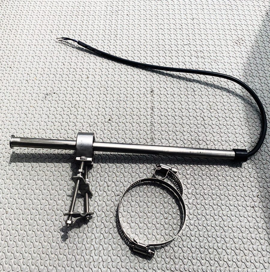
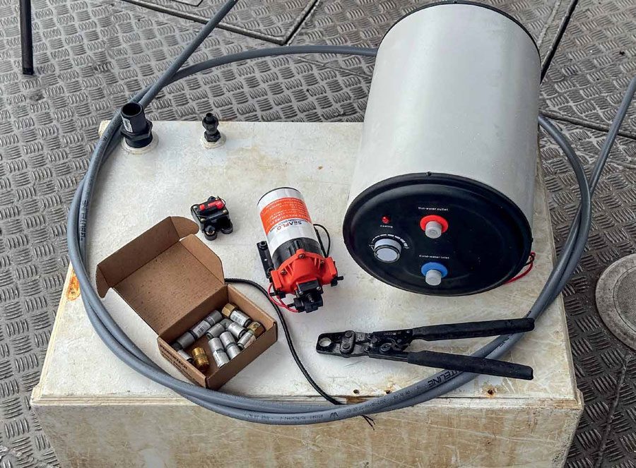
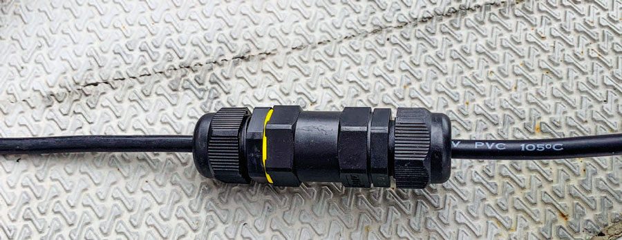
The sender is relatively simple, with a collar that slides along the tube. The IP68 fully immersible connector, bottom, is necesary for a join in the wiring that sits out on the boarding platform.
The solution is a sealed, tube-style sender, similar to the sender unit we fitted to our water tank a few months ago. This is a slim design that is clamped to the outside of the steering cylinder. It then has a moving magnetic collar, clamped to the steering ram, that slides over the sealed tube as the outboard moves. The magnet operates a series of reed switches inside the sealed tube, which detect the position and translate that into the direction that the motor is pointing. These units are made by KUS, and although the outboard steering indicator model is not readily available in New Zealand, it can be ordered through most outlets that sell other KUS units.
The installation of the sender unit is fairly simple: a fixed clamp goes around the steering cylinder and holds the tube, and a sliding magnet is clamped to the end of the steering arm. Suitable clamps are provided for both, but it takes a bit of headscratching to work out the best position that won’t impede the steering action and will also not be in the way when the motor is fully tilted up.
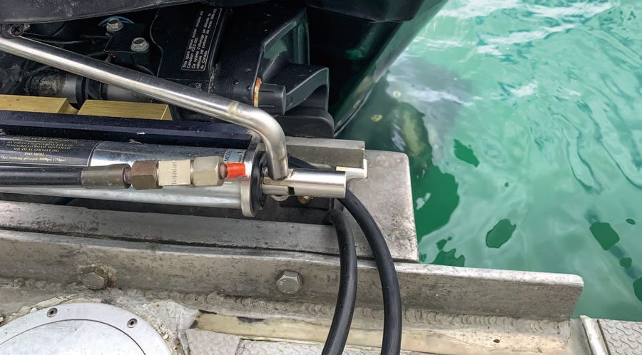
In our case the steering rod itself was almost flush with the end of the cylinder at either end when the steering was at full lock, so we had no place to clamp the magnetic collar. There were a couple of ways we could have solved this but the simplest seemed to be to make a short extension to the steering ram. A piece of stainless tube with the same diameter as the rod was sourced, and a 10mm slot cut into it. A bit of judicious grinding ensued, and to fit it we unscrewed the steering arm and replaced the two existing washers with the extension tube. As can be seen from the photos, the end result is a tidy solution that looks like it was part of the original steering.
After fitting the clamps, we tried a few tilt-and-trim motions of the motor to ensure nothing was jamming. This resulted in a few slight changes to the position of the unit, after which we securely tightened up the clamps. The last part of this job was to cut off the extra bolt length and ensure there were no sharp edges for unwary feet to find when standing on the boarding platform.
The second part of the job involved the electrical connections up to the gauge on the helm. The only frustrating part of the kit was that the tail end of wire on the sender was far too short to reach across the boarding platform into the relatively dry area inside the cockpit. This meant a join in the wire was required, outside on the boarding platform where it will regularly get soaking wet. We needed a solution which was not just waterproof but fully immersible. The meant an IP68 connector, rated fully waterproof for up to 30 minutes at 1.5m of depth. Back to the chandlers!
It is important when planning a watertight connection that the gland on the connector correctly matches the cable. Unfortunately, current global supply chain issues mean that the most readily available twin-core marine cable is flat, but the Amphenol branded IP68 waterproof connectors that are available are only suitable for round cable of between 6 and 8mm in diameter. It took a bit of scurrying around to source marine-grade cable of the right diameter, after which the actual connection was a simple process.

In our boat there was an existing conduit that we could use to pass the cable up through the transom, by threading it down the same tube as the outboard control cables. If this was not available, then a further watertight joint would have been required to safely allow the cable to pass through the transom without allowing any water ingress. Products such as the Scanstrut Deck Seal could have been used to provide a fully waterproof seal. We did not require it since we were able to feed enough cable through the outboard cable duct to reach the helm.
Having sorted out the wiring path, the second half of the installation took about an hour. This included fitting the IP68
connector, feeding the cable through the wiring duct from the transom up to the helm, cutting a suitable hole in the dash and fitting the gauge, and then connecting it all up. A quick test showed everything was working.
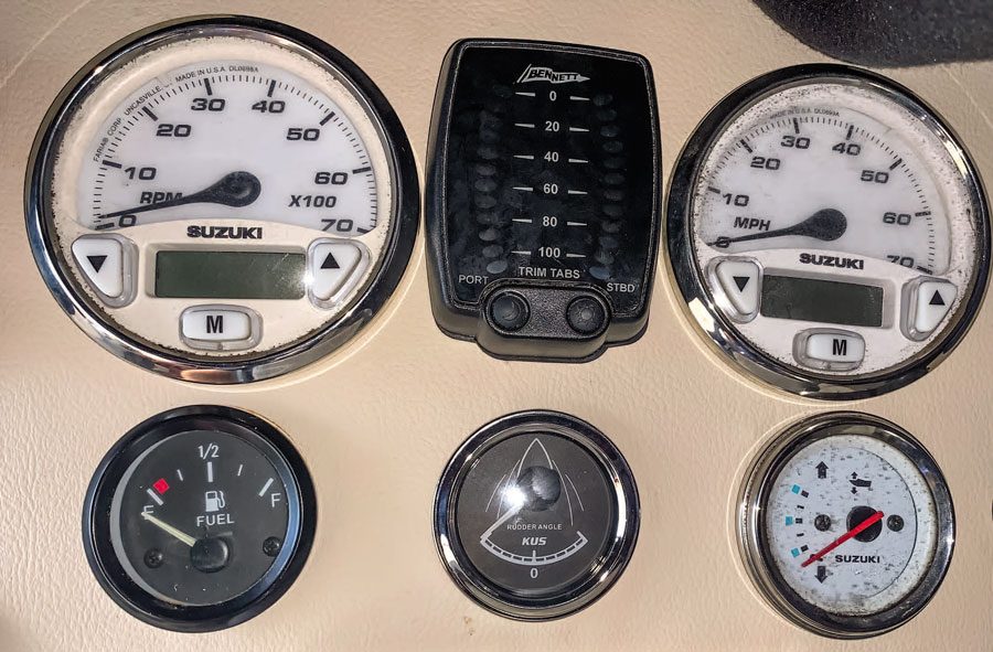
Now for the proof of the pudding. I had installed this on my buddy’s boat since he has challenges whenever he manoeuvres his boat around the marina. His boat is not particularly responsive to the steering, and he sometimes turns the motor the wrong way when he is looking behind him. However, with the new indicator he can simply keep his head facing forward, either looking at the marina ahead or at the helm. The indicator will tell him which way the stern will travel when he puts the motor into gear, so he should find it a lot easier to move her in and out of her berth.
Just as I was finishing the job, my OCD tendencies kicked in and told me the overall layout of the dash was now a mess. Time to make a new helm faceplate and reposition everything. But that is another project for another day… BNZ